The Quick Answer
Time Domain Reflectometry sounds complicated. The principle is not. A radar uses a radio pulse and the time delay of its reflection to find an aircraft's distance. A TDR uses an electrical pulse and the time delay of its reflection to find a cable's fault distance. Same physics, smaller scale.
For network installers, TDR is the difference between knowing exactly which 6-foot section of wall to open and randomly guessing. It is one of the highest-leverage diagnostic tools in the trade.
How TDR Works
The instrument fires a short electrical pulse into one end of the cable. As the pulse travels down the conductor, it sees an impedance roughly constant at the cable's rated value (100 ohms for Cat5e, Cat6, and Cat6A). When the pulse reaches a discontinuity — an open conductor, a short between conductors, a kink, or the natural end of the cable — some of the pulse energy reflects back toward the source.
The TDR measures the elapsed time between firing the pulse and detecting the reflection. Knowing the speed at which the pulse travels through the cable (the velocity of propagation), the instrument calculates the distance to the discontinuity:
- Distance = (round-trip time / 2) × VoP × speed of light
- Pulse travels out to the fault, reflects, and returns. Round-trip time is divided by 2 to get one-way time.
- VoP is typically 0.65 to 0.70 for twisted-pair ethernet cable.
- Speed of light is approximately 300,000 km per second, or 3 × 10⁸ m/s.
The polarity of the reflection tells you the type of fault. An open circuit produces a positive-going reflection. A short circuit produces a negative-going reflection. Lesser impedance changes (kinks, water intrusion, partial damage) produce smaller reflections in either polarity depending on whether the local impedance went up or down.
What TDR Reflections Look Like
A TDR display shows reflection amplitude on the vertical axis and distance on the horizontal axis. The shape and direction of the reflection tells you what kind of fault is at that distance.
Open circuit
An open shows up as a strong positive-going reflection at the fault distance. The full pulse energy bounces back because there is no path forward. If the cable end is properly terminated into a switch port or device, you may see a smaller reflection at the actual cable end (because the device's input impedance is not perfectly matched to 100 ohms). A clean open is unmistakable.
Short circuit
A short shows up as a strong negative-going reflection. The pulse sees zero impedance at the short and reflects with inverted polarity. As with an open, the reflection magnitude is large because most of the pulse energy bounces back.
Kink or partial damage
A bend or crush that has reduced the cable's local impedance (squeezed pairs closer together) produces a small negative-going reflection. A crush that increased local impedance (broke a strand or stretched the cable) produces a small positive-going reflection. These partial faults are often what cause certifier failures on otherwise functional cables — the cable still works for basic data but fails NEXT or return loss specs.
Cable end
If the far end of the cable is open (no device connected), you see a large positive reflection at the cable's full length. If the far end is shorted, you see a large negative reflection. If the far end is terminated into a switch or other device, you may see a smaller reflection because the device input impedance is not perfectly matched.
Step-by-Step: Using TDR on an Ethernet Cable
The procedure is straightforward once you have the right setup. Follow these steps in order.
- Disconnect the cable at both ends. Remove the cable from the switch and from the device or wall jack. TDR works on a passive cable. Active equipment will reflect the pulse and confuse the trace.
- Connect the TDR to one end of the cable. Most network testers with TDR functionality plug into a standard RJ45. Some require a remote unit at the far end for full testing, but for fault location a single-ended test is usually enough.
- Select the cable type. Choose Cat5e, Cat6, or Cat6A on the instrument. This sets the default VoP. For coax or other cable types, select the matching cable family.
- Verify or override the VoP if you have a known length cable. Some testers allow custom VoP entry. If you can test a cable of known length first and adjust VoP until the displayed length matches, you have calibrated the instrument for that exact cable lot.
- Run the TDR test. The instrument fires a series of pulses, averages the results, and displays the trace.
- Read the distance to the strongest reflection. An open or short typically shows the largest reflection. Smaller reflections may indicate kinks or partial faults along the run.
- Test each pair separately. A break may affect only one pair. Test pairs 1-2, 3-6, 4-5, and 7-8 individually if your TDR allows pair-by-pair testing. The pair that shows the fault closest to the connector is usually the failure.
- Walk the cable path and measure. Start from the test point and follow the cable, measuring the reported distance. The fault should be at or very near that point.
Velocity of Propagation Reference
Using the wrong VoP is the most common source of TDR distance errors. The values below are typical for common cable types. Cable manufacturers publish exact values on their datasheets.
| Cable Type | Typical VoP | Notes |
|---|---|---|
| Cat5e UTP | 0.65 - 0.72 | Most common: 0.69 |
| Cat6 UTP | 0.66 - 0.70 | Most common: 0.69 |
| Cat6A UTP | 0.67 - 0.73 | Slightly higher than Cat6 due to larger jacket |
| Cat6A F/UTP shielded | 0.65 - 0.70 | Foil shield slightly affects VoP |
| RG-6 coax | 0.81 - 0.85 | Solid copper or copper-clad steel |
| RG-59 coax | 0.78 - 0.82 | Older video / CCTV applications |
| Phone wire (UTP, 24 AWG) | 0.65 - 0.68 | Quad-twisted pair |
If the TDR reads the cable's full physical length incorrectly (verify by running a TDR on a known-good cable of the same type), adjust the VoP. A 5% error in VoP gives a 5% error in distance.
Practical Field Tips
Theory aside, real-world TDR work has a few quirks. These tips will save time and improve accuracy.
Test from both ends if possible
If the fault distance from end A is 32 meters and from end B is 8 meters, the fault is 32 meters from A and 8 meters from B. Distance from both ends should add up to the total cable length (within VoP error). If they do not, you may have multiple faults or the cable is longer than expected.
Account for patch cords and connectors
The TDR measures from where it connects, not from any logical "starting point." If you connect at the patch panel, the distance includes the patch panel-to-wall jack run, the jack itself, and the wall jack-to-fault distance. Subtract the patch cord length if you connected through one.
Beware of noise on active networks
Even after disconnecting both ends of the cable, a cable that runs near power or active equipment can have induced noise that confuses TDR readings. If the trace is noisy, the instrument may average multiple shots to clean it up. Rerun the test with both ends fully isolated.
Look for multiple reflections
Some faults produce echoes. The pulse travels out, hits the fault, partially reflects, the rest continues, hits the cable end, reflects, comes back, and you see a second reflection at twice the cable length. If you see two reflections, the closer one is the actual fault.
Compare against a known-good run
If your facility has multiple identical cable runs and only one is failing, run TDR on a known-good cable to see what its baseline trace looks like. Anomalies on the failing cable that do not appear on the good one are the faults.
Common Faults TDR Catches
TDR is most useful for finding the kinds of physical damage that wire map alone cannot characterize.
- Staple through the jacket. Common in older installations where cable was stapled to studs. The staple can pierce the jacket and short or break a conductor. TDR shows the fault at the exact distance from the test point.
- Crush at floor joist or beam crossing. A cable run over a sharp edge under load can crush internally. The TDR shows a small reflection at the crush point.
- Rodent damage. Mice and rats chew through cable jackets in attics and crawl spaces. TDR finds the bite location precisely.
- Tight bend or kink. Cable bent past minimum bend radius shows a localized impedance change. The reflection may be small but consistent on repeated tests.
- Splice or unauthorized junction. Sometimes a cable has been cut and reconnected with a coupler or splice. TDR shows the impedance bump at the splice location.
- Water intrusion. Cable in damp environments can absorb moisture, lowering local impedance. TDR shows a stretched reflection over a section of the cable.
- Mid-cable conductor break. A conductor severed in the middle of a run shows as an open at the break distance. Re-termination at both ends will not fix this — the cable must be replaced.
TDR Limitations
TDR is powerful but not magic. There are situations where it cannot give a definitive answer.
- Marginal contacts that work intermittently. A connection that holds during the static TDR pulse but fails under load may not show up. Combine TDR with a flex test or BERT to catch these.
- Faults very close to the test point. Most TDRs have a "dead zone" of the first 1 to 2 meters where reflections from the connector itself swamp any genuine fault reading. Test from the far end if the suspected fault is near the near end.
- Multiple small faults. If the cable has several minor impedance bumps, the trace becomes hard to read. The instrument may report only the strongest reflection.
- Wrong VoP. Distance accuracy depends on correct VoP. If your reported length is way off, recheck the VoP setting before drilling holes in walls.
Tools with TDR Capability
Most modern cable testers and certifiers include built-in TDR or distance-to-fault. Here is what is available across the price range.
Wire Map Tester with Length
Reports total cable length and distance to a fault using TDR principles.
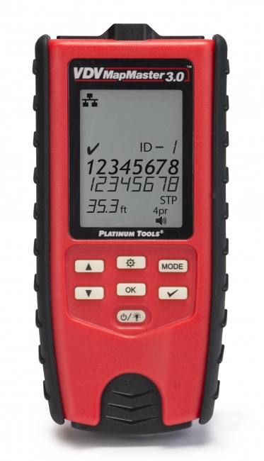
The MapMaster reports cable length and distance-to-open. For most fault location work in a structured cable plant, this resolution is sufficient to identify the right access point. For testing comparison, see Best Network Cable Testers.
Tone Generator for Path Tracing
Once TDR identifies the fault distance, a tone probe helps you trace the cable physically to that location.
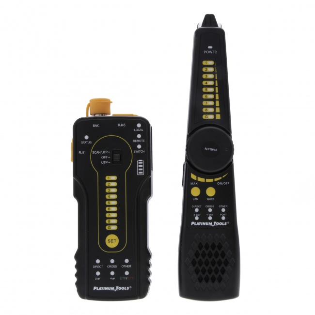
TDR tells you the distance. The tone probe helps you walk that distance along the cable route, especially when cables run through walls, ceilings, and bundles where the path is not visible.
Related Articles
Frequently Asked Questions
What is TDR and how does it find cable faults?
TDR stands for Time Domain Reflectometry. It works by sending a fast electrical pulse down the cable and measuring how long it takes for the pulse to reflect back from any impedance discontinuity, such as an open, a short, or a kink. Because the speed of the pulse through the cable is known (the velocity of propagation, or VoP), the time delay can be converted to a distance, telling you exactly how far along the cable the fault is.
How accurate is TDR for finding cable breaks?
TDR accuracy depends on the velocity of propagation setting and the resolution of the instrument. With the correct VoP for the cable type, modern handheld TDRs are typically accurate to within a few percent of the actual distance. For a 50-meter run, that means accuracy within about 1 to 2 meters. For higher precision, use a certifier-grade TDR or calibrate with a cable of known length.
Can I use TDR to find a fault in a buried or in-wall cable?
Yes. TDR is the standard method for locating faults in cables that cannot be visually inspected. Connect the TDR to one end of the cable, run the test, and the result tells you the distance from the test point to the fault. You can then measure that distance along the cable path to locate the access point closest to the fault for repair.
What is velocity of propagation and why does it matter for TDR?
Velocity of propagation (VoP) is the speed at which an electrical signal travels through a cable, expressed as a fraction or percentage of the speed of light in vacuum. Typical Cat6 VoP is around 0.69 (69%). The TDR uses this value to convert reflection time to physical distance. If the VoP setting is wrong, the calculated fault distance will be wrong by the same percentage.
Do I need a separate TDR or can my cable tester do it?
Many modern cable testers and certifiers include a TDR or distance-to-fault feature. A dedicated TDR has higher resolution and is preferred for precise fault location work, but a built-in TDR in a tester like the VDV MapMaster is sufficient for most field work. The built-in versions can typically locate the fault within a meter or two, which is good enough to find the right access point for repair.
Find the Fault, Not the Drywall
The right TDR-equipped tester turns cable fault location from a destructive guessing game into a measured cut. Browse testers with built-in TDR.